The question is often asked: “Can I use 120 film in a 220 back?”
There are several standard answers given, however here we will explore the truth behind these responses—and explain what you actually need to consider when using a 220 film back. Before starting though, if you aren’t familiar with the differences between 120 and 220 film, take a look at the diagram further down this page.
Myth #1: 120 film in a 220 back will result in out of focus exposures
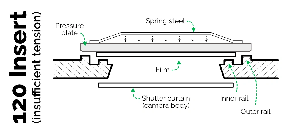
This is often repeated, but untrue. The premise is that the difference in thickness between 120 and 220 film results in the 120 film not sitting flat against the pressure plate in a 220 back. Therefore, the film does not align perfectly with the camera’s focal plane. However, the slight degradation of sharpness that has been observed in the past can affect either 120 or 220 inserts. It is due to reduced tension in the spring steel that sits behind the pressure plate.
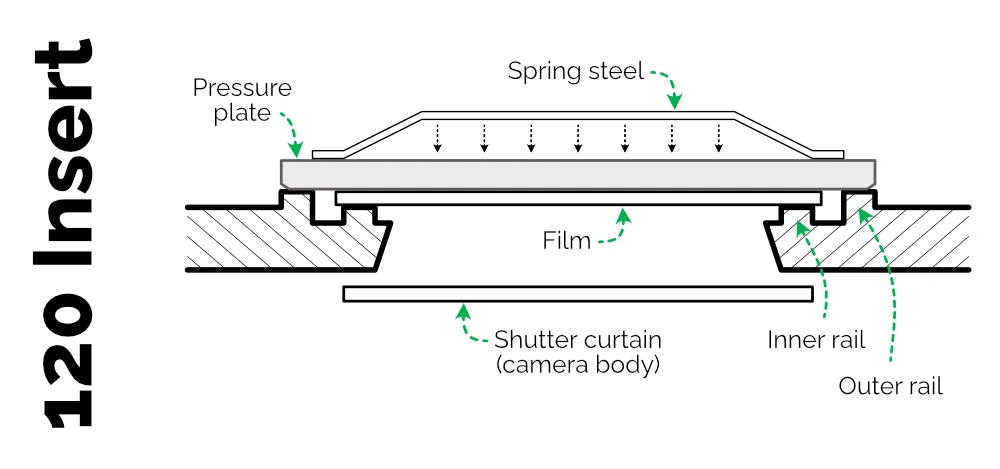
To understand why, we first need to look at the construction of the 120 and 220 film backs. If you aren’t familiar with the components of Bronica ETR System film backs, have a quick look at that first.
Firstly, open the back and remove the insert. Take a look at the inside of the back frame, on the short edges of the opening where the dark slide is inserted. Here you will see two metal rails on either side of the opening.
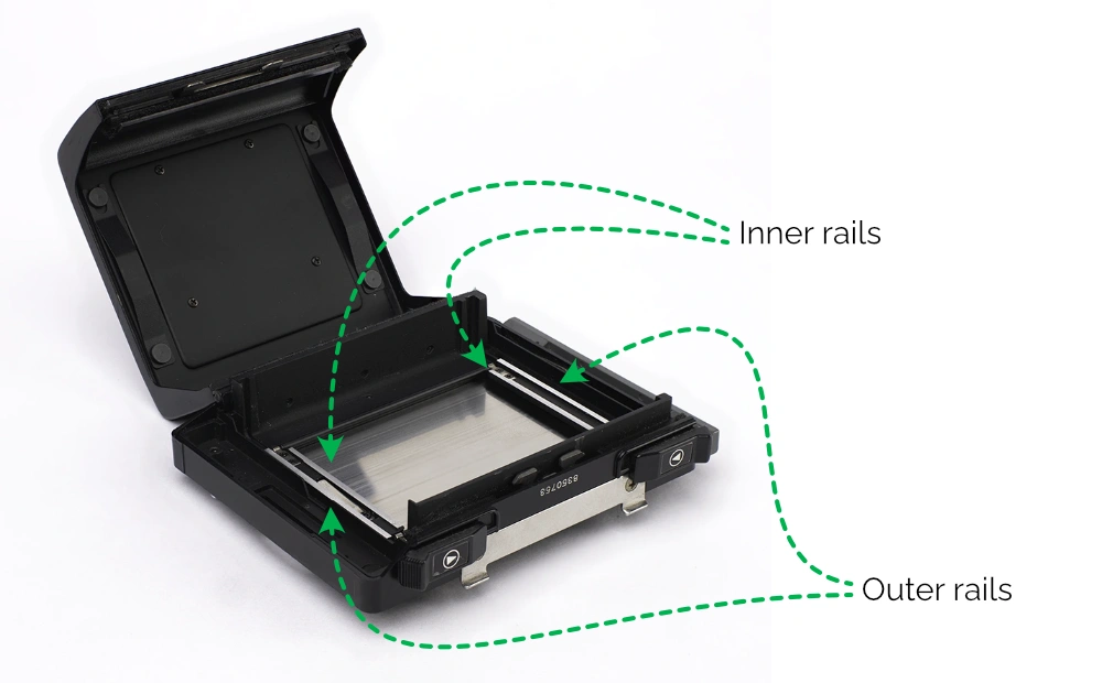
The inner, slightly shorter rail is designed to hold the film firm against the pressure plate. The outer, slightly longer rail, is designed to regulate the gap between the backing plate in the inner rails. There is only one type of film back frame, so whether you have a 120 back or a 220 back, this will be identical.
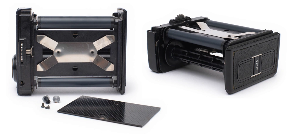
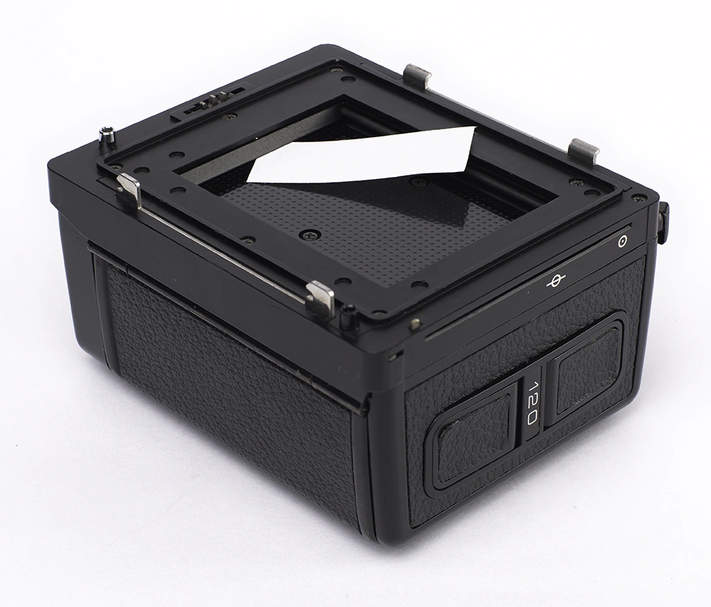
Now take a look at the front of the insert—the side with the pressure plate, that faces the camera body. At the top and bottom you will see the two counter rollers, larger at the top and smaller at the bottom, and between these the pressure plate.
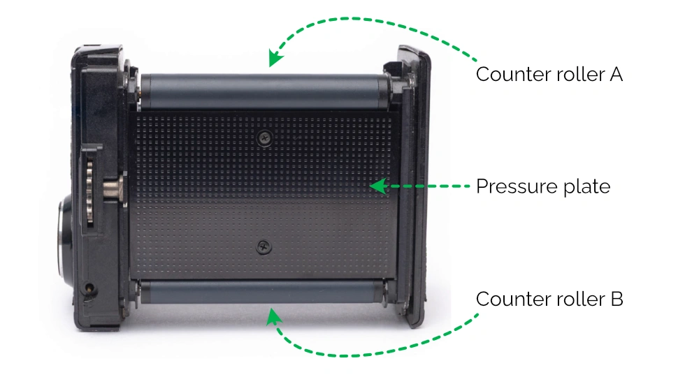
Push down on the pressure plate and you will notice it has some give, before moving back into place when you release your finger. This happens because of an X-shaped piece of spring steel that sits beneath the
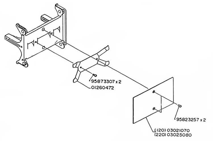
If you removed the two screws holding the pressure plate, you will see the spring steel beneath. Please don’t do this unless you are confident you can put it back together!
So if we put all this information together, we can now see what it looks like when film is being wound through a Bronica ETR system film back, as demonstrated in the following diagram.
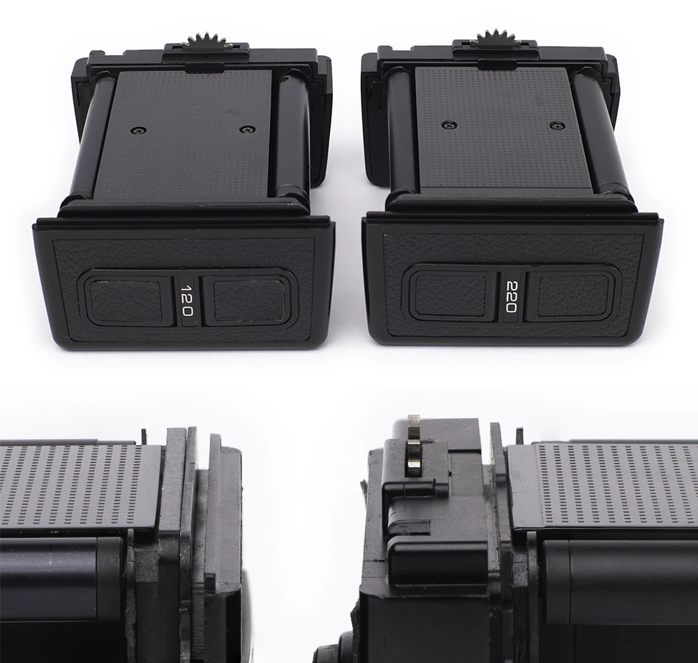
So far we’ve been looking at 120 film back inserts, but what we are interested in here are the 220 inserts. There are only four differences between the 120 and 220 inserts for the Bronica ETR (you can see these for yourself in the ETRSi Film Back-Ei Repair Manual):
- the film indicator plate on the left side cover (which reads either “120” or “220);
- the counter gear located at the base of the Counter Roller A axle;
- the dividing plate set which shows the exposure counter; and
- the pressure plate.
The first difference is purely cosmetic. The second two are internal changes to the gearing ratio, allowing the backs to display either 15 exposures (for 120 film) or 30 exposures (for 220 film) in the counter window. Only the final difference has anything to do with the positioning of film within the back.
The pressure plate of a 220 film insert has two very slight depressions, about 3mm wide each, running down the short edges of the plate.
If you look carefully, you will see that these depressions align with the outer, longer rail on the film back frame. The effect of the depression is that the pressure plate sits slightly closer to the inner rails, reducing the available gap for the film. This makes perfect sense, as we know that 220 film is thinner (due to not having backing paper) than 120 film.
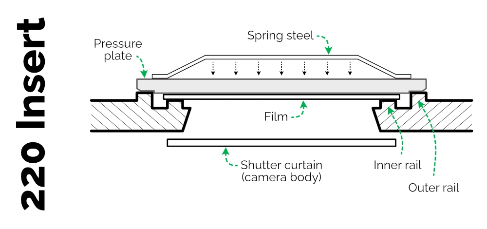
So the reality is that the thicker 120 film will have less of a gap—not more—available between the pressure plate and the inner rails. And the emulsion side of the film will be located in exactly the same place—the film plane—as this is dictated by the inner rails. If anything, the film will be slightly harder to wind through the back. This has been reported by some users, but it’s not something I personally have ever particularly noticed.
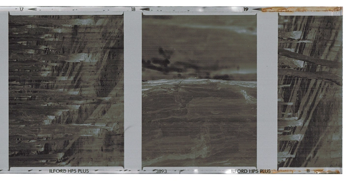
So why have some people experienced a degradation in sharpness when using 220 backs?
What you will find after having looked at enough ETR film backs, is that the alignment of the pressure plate does not vary between 120 and 220 back inserts, but rather it varies based on the age and condition of the insert.
If you remove the insert and look at the pressure plate side on, you should see that the plate sits just above the height of the counter roller. By pushing down on the plate, you should see that it moves below the height of the roller.
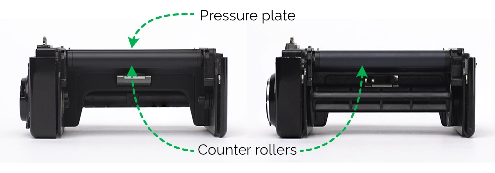
If the plate started below the height of the roller, then it is likely the spring steel behind the plate is no longer providing enough tension, and it may have some impact on the sharpness of your exposures (whether it is enough to be observable is a matter of opinion!)
You can also verify the tension of the pressure plate for an individual back frame and insert combination by assembling the back, removing the dark slide (a bit fiddly on Ei generation backs), and verifying that there is no obvious gap between the pressure plate and the film track on the short side of the frame opening.
To test this gap, you can use standard printing paper (20lb/75gsm). Two to three sheets of this paper is about the same thickness as 120 film and its backing paper (200-280μm). You should be able to slide one thickness of paper between the pressure plate and film track, with no resistance. Two thicknesses should resist slightly, and three thicknesses should not be possible without pushing down on the pressure plate slightly to reduce resistance. If you can easily slide two or more thicknesses of paper in, there is not enough tension behind the pressure plate and the insert needs servicing or replacement.
Myth #2: 220 film has a longer leader
Well this is actually true—but the leader length is not important. What matters is the length between the alignment arrow on the film back paper, and the position of the first exposure on the film.
The leader is the portion of paper backing before the start of the film itself. The ISO 732 standard requires the leader length up to the start of the first exposure to be:
- 120 film: 468mm (±20mm)
- 220 film: 598.5mm (±25.5mm)
What makes a difference for film loading is the distance between the alignment arrow and the first exposure position, which is defined as:
- 120 film: 211mm
- 220 film: 205.5mm (±5.5mm)
Based on this, the distance could be up to 11mm shorter for 220 film – but it could also be the same as 120 film.

It is sometimes suggested that you shouldn’t wind the film all the way up to the alignment arrow in the 220 insert—however, there is no reason to do this. Aligning the arrows will result in having slightly less unexposed film before the first exposure, compared to 120 film, and allows you to take 15 full exposures. And, if you forget to keep an eye on the exposure counter, you’ll usually get a bonus 16th exposure, cut in half at the end of the film!
Myth #3: Frame spacing will be larger
The logic behind this myth is sound—120 film is thicker than 220 film, due to the backing paper behind the film. Therefore, it is logical that for each subsequent rotation of the take-up spool, slightly more 120 film would be taken up than if the back was loaded with thinner 220 film. However, this assumes that the mechanism that determines how much film to advance after each exposure is based on a number of rotations of the take-up spool.
If the thickness of film on the take-up spool affected the gap between each exposure, we would expect to see the gaps gradually increasing with each additional exposure on the film. However, what we tend to see with Bronica ETR cameras are variable gaps throughout the length of the exposed film, ranging between 5 and 11mm, with no obvious pattern of increase (see table below for some examples).
| Back & film used | 220 back (Ilford HP5) | 120 back (Ilford HP5) | 120 back (Kodak Tri-X) |
| Gap after 1st exposure | 10.5mm | 8mm | 9mm |
| …after 2nd exposure | 11mm | 10mm | 10mm |
| …3rd | 5mm | 7mm | 7mm |
| 4th | 7,5mm | 8.5mm | 7.5mm |
| 5th | 9mm | 6mm | 6mm |
| 6th | 6mm | 7mm | 7mm |
| 7th | 6mm | 7.5mm | 7mm |
| 8th | 8,5mm | 6.5mm | 6.5mm |
| 9th | 7mm | 7mm | 8mm |
| 10th | 7mm | 8mm | 5.5mm |
| 11th | 7mm | 6mm | 7mm |
| 12th | 8mm | 8mm | 9mm |
| 13th | 6.5mm | 8mm | 6mm |
| 14th | 6.5mm | 8mm | 7.5mm |
| 15th | 7mm | n/a | n/a |
The truth behind this myth is that rotation of the take-up spool is not the mechanism used by the Bronica ETR system to determine how far to advance the film. Rather, it is the rotation of the counter roller as the film moves onto the film plane. This is unaffected by the thickness of the film, and explains why there is no increase in gaps between exposures.
Consideration: the back thinks you have 30 exposures
This is the one thing that you do need to worry about!
Keep an eye on the exposure counter—the back will think you have 30 exposures. After the 15th frame, the camera will continue allowing you to take exposures, but there won’t be any film left to expose. You will need to dry fire the camera until the back agrees the film has been completely used, before unloading the film.